Voltage Measurement
Overview
The Voltage Measurement sample demonstrates using Nordic configurations of the Zephyr ADC infrastructure to measure the voltage of the device power supply.
The measurement circuit contains a voltage divider made of two resistors. AIN0 measures the voltage over the lower resistor and P1.14 is used to enable the voltage measurement. The voltage measurement circuitry is shown in the following figure:
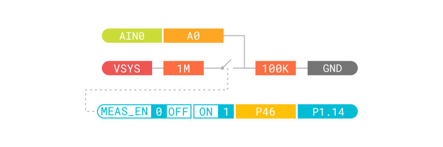
The board devicetree has a power_vsys_in node with compatible voltage-divider. The voltage is measured using that divider. The devicetree node describing is shown below:
power_vsys_in {
    compatible = "voltage-divider";
    io-channels = <&adc 0>;
    output-ohms = <100000>;
    full-ohms = <(1000000 + 100000)>;
    power-gpios = <&gpio1 14 0>;
};
Requirements
Before you start, check that you have the required hardware and software:
- 1x nRF52840 Connect Kit
- 1x USB-C Cable
- A computer running macOS, Linux, or Windows 7 or newer
Building the sample
Before you start building, remember to set up the environment first.
Use the following steps to build the Voltage Measurement sample on the command line.
-
Open a terminal window.
-
Go to
my-workspace/ncs-playgrounddirectory created in the Setting up the environment section. -
Build the sample using the
westcommand, specifying the board (following the-boption) asconnectkit_nrf52840:Tip
The
-p alwaysoption forces a pristine build, and is recommended for new users. Users may also use the-p autooption, which will use heuristics to determine if a pristine build is required, such as when building another sample. -
After running the
west buildcommand, the build files can be found inbuild/zephyr.
Flashing the firmware
The sample is designed to work with the UF2 Bootloader, so that you can easily flash the sample using the UF2 Bootloader. The firmware can be found in build/zephyr with the name zephyr.uf2.
To flash the firmware, complete the following steps:
-
Push and hold the USER button and plug your board into the USB port of your computer. Release the USER button after your board is connected. The RGB LED turns green.
-
It will mount as a Mass Storage Device called UF2BOOT.
-
Drag and drop
zephyr.uf2onto the UF2BOOT volume. The RGB LED blinks red fast during flashing. -
Reset the board and the sample will start running.
Testing
After flashing the firmware to your board, complete the following steps to test it:
- Connect nRF52840 Connect Kit to your computer using the USB-C Cable.
-
Open up a serial terminal, specifying the correct serial port that your computer uses to communicate with the board:
-
Observe the output of the terminal. You should see the output, similar to what is shown in the following:
