ADC
The ADC sample demonstrates using the analogio module to measure the voltage of the device power supply.
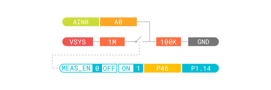
The measurement circuit contains a voltage divider made of two resistors. AIN0 (alias A0) measures the voltage over the lower resistor and P1.14 (alias MEAS_EN) is used to enable the voltage measurement. The voltage measurement circuitry is shown in the following figure:
Requirements
Before you start, check that you have the required hardware and software:
- nRF52840 Connect Kit running the CircuitPython firmware
- 1x USB-C Cable
- Mu Editor
- A computer running macOS, Linux, or Windows 7 or newer
Running the code
To run the code, complete the following steps:
- Connect nRF52840 Connect Kit to your computer using the USB-C Cable.
- Start Mu Editor, click Load to open
code.pyin the CIRCUITPY drive. -
Copy and paste the following code into
code.pyand click Save: -
Your code will run as soon as the file is done saving. Click Serial on Mu Editor's Top Menu to open a serial console. You should see the console output, similar to what is shown in the following:
-
You can also use the plotter for data inspection. Click Plotter on Mu Editor's Top Menu to open up a plotter pane:
