Espruino
A JavaScript interpreter for microcontrollers. It is designed for devices with as little as 128kB Flash and 8kB RAM.
![]()
Introduction
Espruino is a JavaScript interpreter for microcontrollers. It is designed for devices with as little as 128kB Flash and 8kB RAM.
Unlike other boards that run JavaScript, Espruino fits everything it needs into single chip. This makes it affordable, reliable, and power efficient - allowing it to run for years on a battery.
Espruino plugs in to your computer by USB and appears as a serial device. No drivers, and no special software. Just run a terminal application and start writing code right away!
Espruino comes with its own IDE which installs in seconds and provides a modern Syntax Highlighted editor with code completion. It even automatically loads any modules you need from the internet.
The optional graphical editor makes it quick and easy to create simple devices, even if you've never programmed before.
For more information, please visit Espruino Official site.
Getting Started
This section will show you how to getting started with Espruino using the nRF52832-MDK board. The instructions are provided for macOS. The steps should be similar for other platforms.
Ready? Let's start!
Flashing Espruino
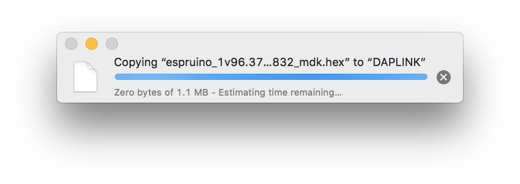
Before we begin coding, we need to program the board with the Espruino firmware. You can get the latest Espruino firmware with the name espruino_x.x_nrf52832_mdk.hex in the directory ./nrf52832-mdk/firmware/espruino/.
Connect the nRF52832-MDK to one of your PC's USB host ports. Then drag and drop the hex file into the DAPLINK removable drive.
When programming is completed, the unit will be re-detected by the computer. Espruino will run after pressing the RESET button.
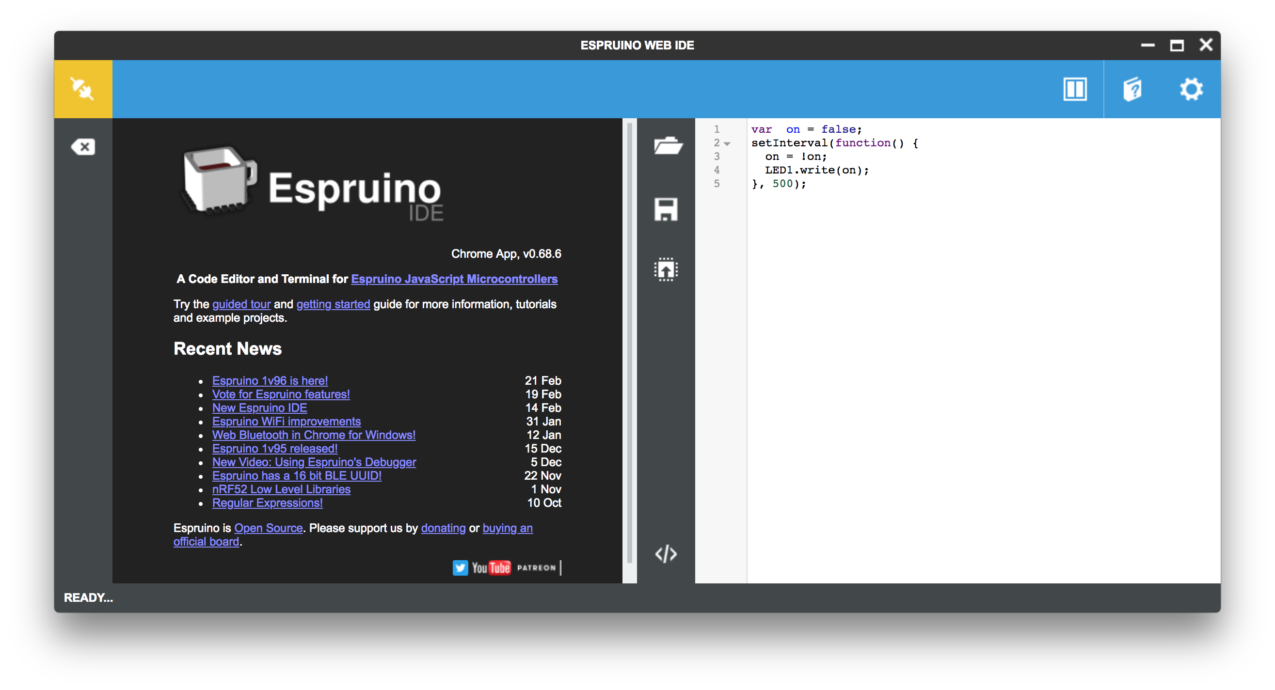
Installing Espruino Web IDE
We recommend that you use the Chrome Web App. It has a bunch of extra features, including graphical editor. You can do so by performing the following steps:
-
Install the Chrome Web Browser if you don't have one.
-
Click here to get the Espruino Web IDE and click
+FREEin the top right to install it. -
Run Espruino Web IDE from Chrome's home screen (or the App Launcher)
Connecting your board
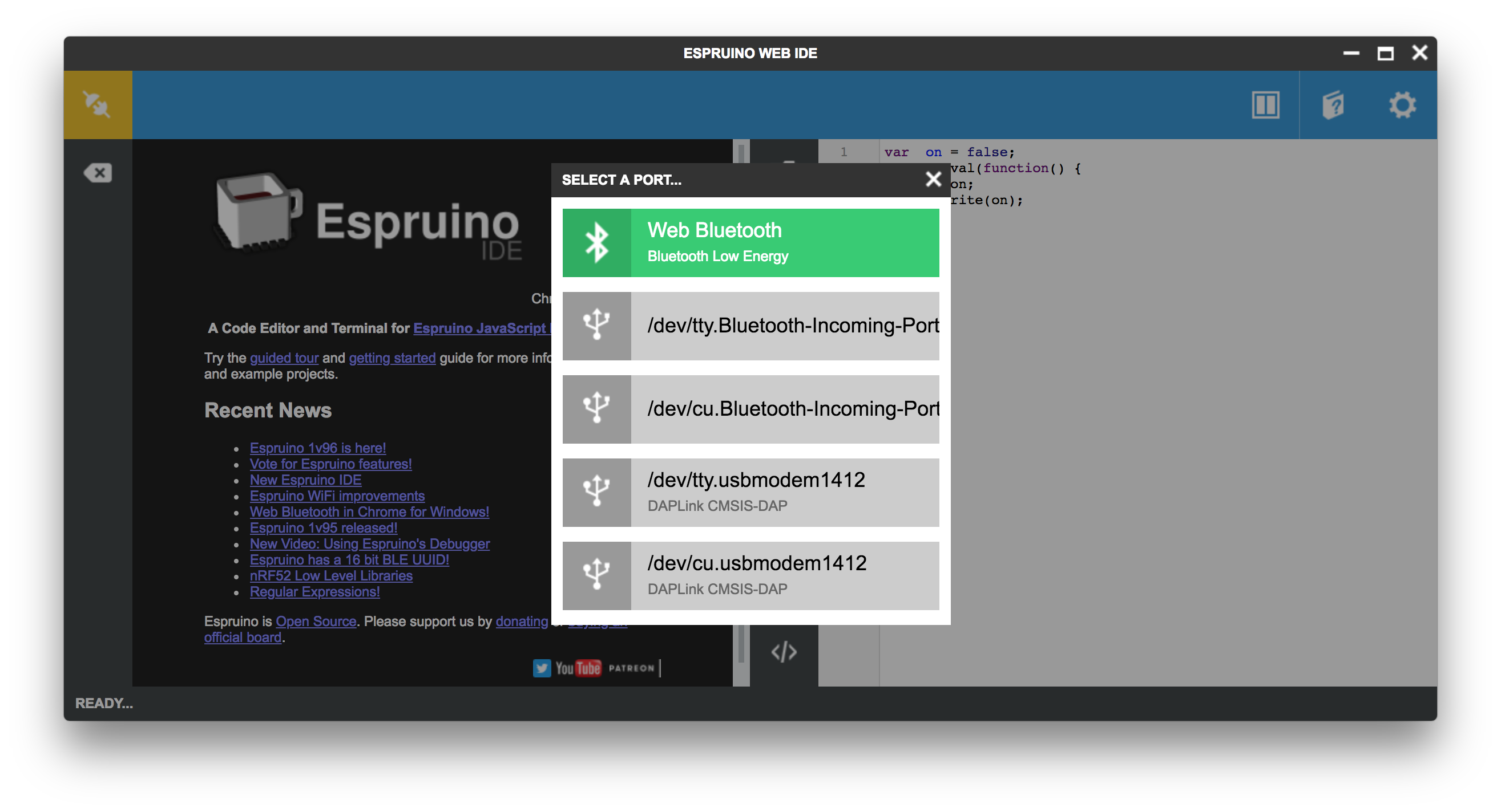
Now you can connect your board with the Espruino Web IDE.
Click the Connect/Disconnect icon in the top left.
Choose Web Bluetooth if your PC has Bluetooth low energy supported, or choose serial port connection(For example, /dev/tty.usbmodem1412):
For Web Bluetooth connection, you should pair the device next:
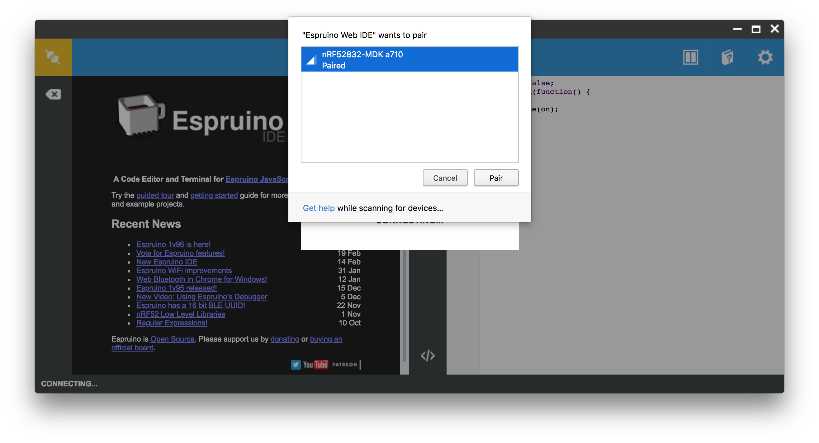
After that, it will show the board is connected:
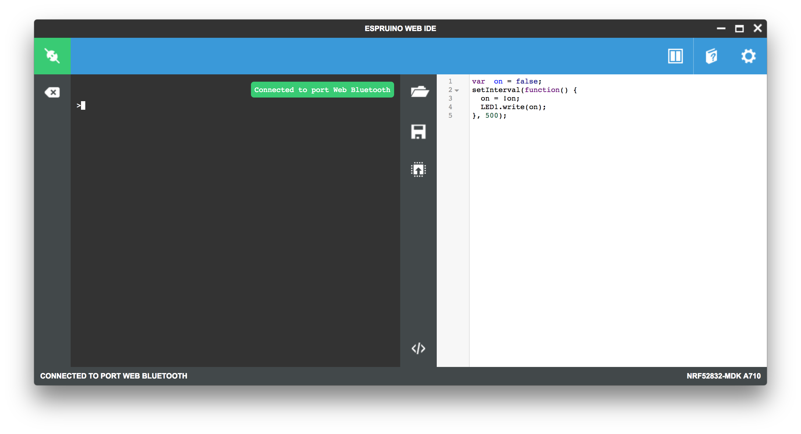
Writing & Running your code
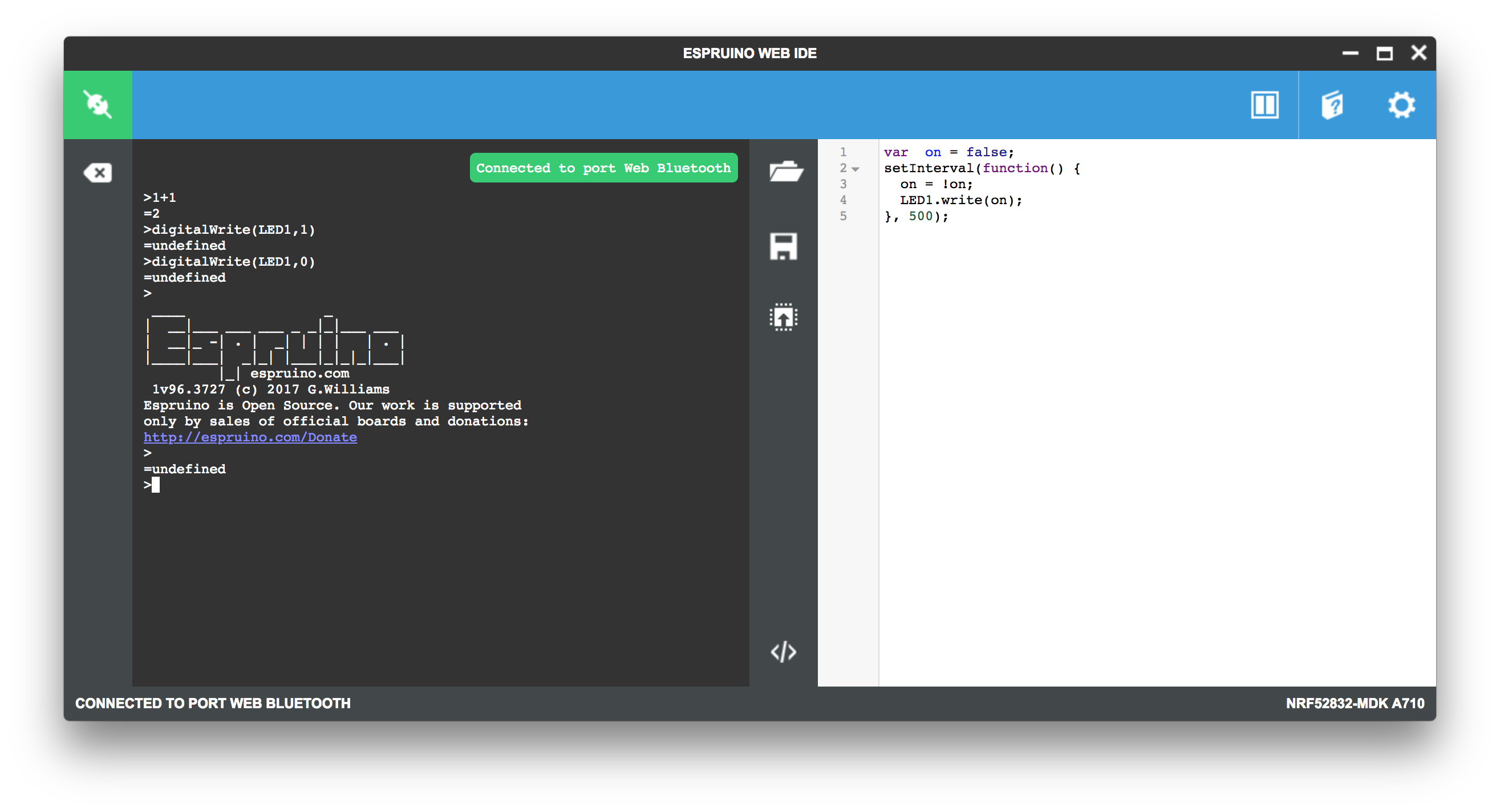
Try typing the following in the left-hand side of the Web IDE, and press Enter after it:
> 1+1

> digitalWrite(LED1,1)

> digitalWrite(LED1,0)
You can also write your code in the right-hand side of the Web IDE. Will use the blinky example here to keep it simple.
var  on = false;
setInterval(function() {
  on = !on;
  LED1.write(on);
}, 500);
Click the Upload icon to run the example on your board. Observe that the GREEN LED is blinking.
That's it. Now you've got an idea of how to use Espruino.
How to update Espruino firmware
Over time, more features will be added to the Espruino firmware. You may want to update the latest firmware. This section will show how to update the latest firmware by the following options:
Drag-n-drop Programming
The latest firmware is located in the directory firmware/espruino/ of the repository nrf52832-mdk. For example, espruino_1v96.3727_nrf52832_mdk.hex.
Connect the nRF52832-MDK to one of your PC's USB host ports. Then drag and drop the hex file into the DAPLINK removable drive.
When programming is completed, the unit will be re-detected by the computer. Espruino will run after pressing the RESET button.
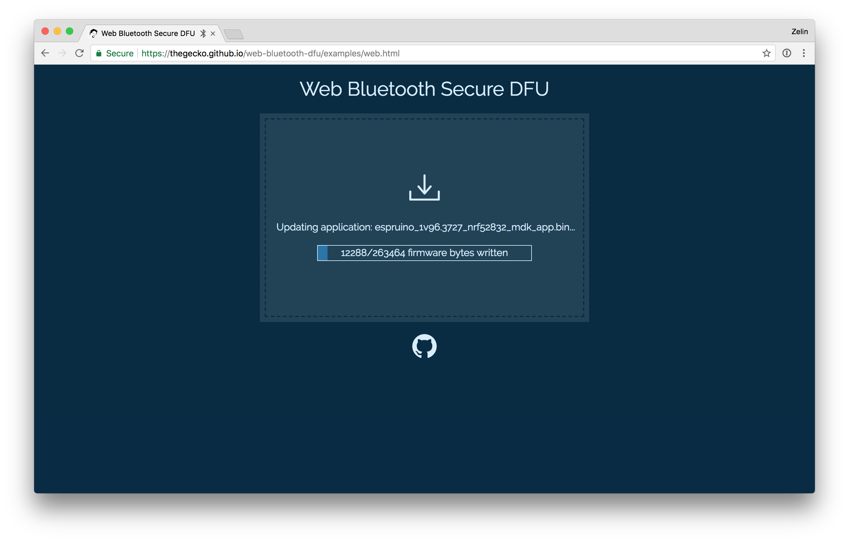
Using Web Bluetooth Secure DFU
The released firmwares support Bluetooth Secure DFU feature. If your PC has Bluetooth low energy supported, you can update the firmware by performing the following steps:
-
Start Chrome Web Browser, go to the page: Web Bluetooth Secure DFU.
-
Wire
P18to3V3, and the power up your board. Observe that the BLUE and RED LEDs are on. Remove the wire, observe that the BLUE is on. It shows that the board is at DFU mode. -
Choose the firmware package or drag it to the page. The latest firmware package is located in nrf52832-mdk/firmware/espruino/ with the name
espruino_x.x_nrf52832_mdk.zip. -
Select the device with the name
DfuTargand pair it. Observe that the RED is on, showing that it's uploading. Waiting update complete.
How to build Espruino
This section will show you how to build your own Espruino firmware.
Setting up the development environment
The GNU Arm Embedded toolchains is needed to build Espruino.
Download and install the GNU Arm Embedded toolchains. Then make sure to add the path to your toolchain to your OS PATH environment variable:
<path to install directory>/gcc-arm-none-eabi-6-2017-q1-update/bin
Adding the path makes it possible to run the toolchain executables from any directory using the terminal. To verify that the path is set correctly, type the following in your terminal:
$ arm-none-eabi-gcc --version
Note
The latest version of GNU Arm Embedded toolchain maybe not work fine, but you can just have a try.
Adding support for nRF52832-MDK
Clone the official repository from Espruino:
$ git clone https://github.com/espruino/Espruino.git
To add support for nRF52832-MDK, you must create a support file with the name NRF52832_MDK.py. This file must be located in a directory in the ./Espruino/boards/ path.
import pinutils;

info = {
 'name' : "nRF52832-MDK",
 'link' :  [ "https://wiki.makerdiary.com/nrf52832-mdk/" ],
  # This is the nRF52832-MDK
 'default_console' : "EV_SERIAL1",
 'default_console_tx' : "D20",
 'default_console_rx' : "D19",
 'default_console_baudrate' : "9600",
 'variables' : 2250, # How many variables are allocated for Espruino to use. RAM will be overflowed if this number is too high and code won't compile.
 'bootloader' : 1,
 'binary_name' : 'espruino_%v_nrf52832_mdk.hex',
 'build' : {
   'optimizeflags' : '-Os',
   'libraries' : [
     'BLUETOOTH',
     'NET',
     'GRAPHICS',
     'CRYPTO',
     'NFC',
     'NEOPIXEL'
   ],
   'makefile' : [
     'DEFINES+=-DHAL_NFC_ENGINEERING_BC_FTPAN_WORKAROUND=1', # Looks like proper production nRF52s had this issue
     'DEFINES+=-DCONFIG_GPIO_AS_PINRESET', # Allow the reset pin to work
     'DEFINES+=-DBLUETOOTH_NAME_PREFIX=\'"nRF52832-MDK"\'',
     'DFU_PRIVATE_KEY=targets/nrf5x_dfu/dfu_private_key.pem',
     'DFU_SETTINGS=--application-version 0xff --hw-version 52 --sd-req 0x8C'
   ]
 }
};

chip = {
  'part' : "NRF52832",
  'family' : "NRF52",
  'package' : "QFN48",
  'ram' : 64,
  'flash' : 512,
  'speed' : 64,
  'usart' : 1,
  'spi' : 3,
  'i2c' : 2,
  'adc' : 1,
  'dac' : 0,
  'saved_code' : {
    'address' : ((118 - 10) * 4096), # Bootloader takes pages 120-127, FS takes 118-119
    'page_size' : 4096,
    'pages' : 10,
    'flash_available' : 512 - ((31 + 8 + 2 + 10)*4) # Softdevice uses 31 pages of flash, bootloader 8, FS 2, code 10. Each page is 4 kb.
  },
};

devices = {
  'BTN1' : { 'pin' : 'D18', 'pinstate' : 'IN_PULLDOWN' }, # Pin negated in software
  'LED1' : { 'pin' : 'D22', 'inverted' : False }, # Pin negated in software
  'LED2' : { 'pin' : 'D23', 'inverted' : False }, # Pin negated in software
  'LED3' : { 'pin' : 'D24', 'inverted' : False }, # Pin negated in software
  'RX_PIN_NUMBER' : { 'pin' : 'D19'},
  'TX_PIN_NUMBER' : { 'pin' : 'D20'},
  'CTS_PIN_NUMBER' : { 'pin' : 'D7'},
  'RTS_PIN_NUMBER' : { 'pin' : 'D5'},
  # Pin D22 is used for clock when driving neopixels - as not specifying a pin seems to break things
};

# left-right, or top-bottom order
board = {
  'left' : [ 'VIN', '5V', 'GND', 'PD4','PD5','PD6','PD7','PD8','PD9','PD10','PD11','PD12','PD13','PD14','PD15','PD16','PD17','PD18'],
  'right' : [ '3V3', 'GND', 'RST', 'CLK', 'DIO','TDO','TDI', 'TXD','RXD','PD3','PD2','PD31','PD30','PD29','PD28','PD27','PD26','PD25'],
};
board["_css"] = """
""";

def get_pins():
  pins = pinutils.generate_pins(0,31) # 32 General Purpose I/O Pins.
  pinutils.findpin(pins, "PD0", True)["functions"]["XL1"]=0;
  pinutils.findpin(pins, "PD1", True)["functions"]["XL2"]=0;
  pinutils.findpin(pins, "PD5", True)["functions"]["3.3"]=0;
  pinutils.findpin(pins, "PD6", True)["functions"]["3.3"]=0;
  pinutils.findpin(pins, "PD7", True)["functions"]["3.3"]=0;
  pinutils.findpin(pins, "PD8", True)["functions"]["3.3"]=0;
  pinutils.findpin(pins, "PD9", True)["functions"]["NFC1"]=0;
  pinutils.findpin(pins, "PD10", True)["functions"]["NFC2"]=0;
  pinutils.findpin(pins, "PD13", True)["functions"]["3.3"]=0;
  pinutils.findpin(pins, "PD14", True)["functions"]["3.3"]=0;
  pinutils.findpin(pins, "PD15", True)["functions"]["3.3"]=0;
  pinutils.findpin(pins, "PD16", True)["functions"]["3.3"]=0;
  pinutils.findpin(pins, "PD17", True)["functions"]["3.3"]=0;
  pinutils.findpin(pins, "PD18", True)["functions"]["3.3"]=0;
  pinutils.findpin(pins, "PD19", True)["functions"]["RXD"]=0;
  pinutils.findpin(pins, "PD20", True)["functions"]["TXD"]=0;
  pinutils.findpin(pins, "PD22", True)["functions"]["LED_1"]=0;
  pinutils.findpin(pins, "PD23", True)["functions"]["LED_2"]=0;
  pinutils.findpin(pins, "PD24", True)["functions"]["LED_3"]=0;
  pinutils.findpin(pins, "PD2", True)["functions"]["ADC1_IN0"]=0;
  pinutils.findpin(pins, "PD3", True)["functions"]["ADC1_IN1"]=0;
  pinutils.findpin(pins, "PD4", True)["functions"]["ADC1_IN2"]=0;
  pinutils.findpin(pins, "PD5", True)["functions"]["ADC1_IN3"]=0;
  pinutils.findpin(pins, "PD28", True)["functions"]["ADC1_IN4"]=0;
  pinutils.findpin(pins, "PD29", True)["functions"]["ADC1_IN5"]=0;
  pinutils.findpin(pins, "PD30", True)["functions"]["ADC1_IN6"]=0;
  pinutils.findpin(pins, "PD31", True)["functions"]["ADC1_IN7"]=0;
  # everything is non-5v tolerant
  for pin in pins:
    pin["functions"]["3.3"]=0;
  #The boot/reset button will function as a reset button in normal operation. Pin reset on PD21 needs to be enabled on the nRF52832 device for this to work.
  return pins
As an option, you can just clone my repository forked from the official. I have added support for nRF52832-MDK.
$ git clone https://github.com/makerdiary/Espruino.git
Building Espruino firmware
Now you can try to build the Espruino firmware using the following options:
Open terminal and change directory to:
$ cd <Espruino git clone location>/Espruino
Build everything, you will get a .hex file:
$ make clean && BOARD=NRF52832_MDK RELEASE=1 make
Build DFU firmware package, you will get a .zip file:
$ make clean && DFU_UPDATE_BUILD=1 BOARD=NRF52832_MDK RELEASE=1 make
Now you can program your board by following the section: How to update Espruino firmware.
Reference
- Espruino Official site
- Espruino API Reference
- Espruino Modules
- Espruino Official Repo
- Espruino forked by makerdiary
Create an Issue
Interested in contributing to this project? Want to report a bug? Feel free and click here: