Getting Started Out of the Box
Introduction
This section describes how to run the Out of Box Demo without going through the complete toolchain installation.
The pre-installed demo running on the Pitaya Go board is controlled with Command Line Interface (CLI) over USB CDC ACM or Bluetooth Low Energy. You can set the LED color, get the chip temperature or control the NFC Tag, using the built-in commands. The application also allows you to connect Pitaya Go to a Wi-Fi network and ping a host in the public network.
Included in the Box
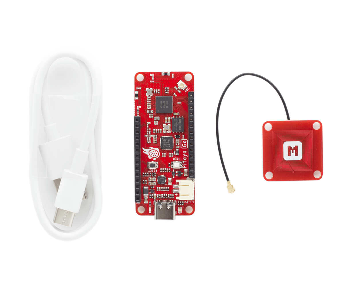
Your Pitaya Go box includes:
- 1x Pitaya Go board
- 1x NFC-A PCB Antenna with MHF I connector
- 1x USB-C Cable
Assemble the Hardware
-
Attach the NFC-A PCB Antenna to the U.FL connector. The connector is marked NFC.
-
Plug in the USB-C cable between your computer and the USB-C Connector.
-
Observe that the PG (Power Good) indicator is lit, and the RGB LED is blinking green.
Set Up with Terminal
Terminal applications (for example PuTTY or screen) run on your host PC. They provide a window where you can interact with the device.
-
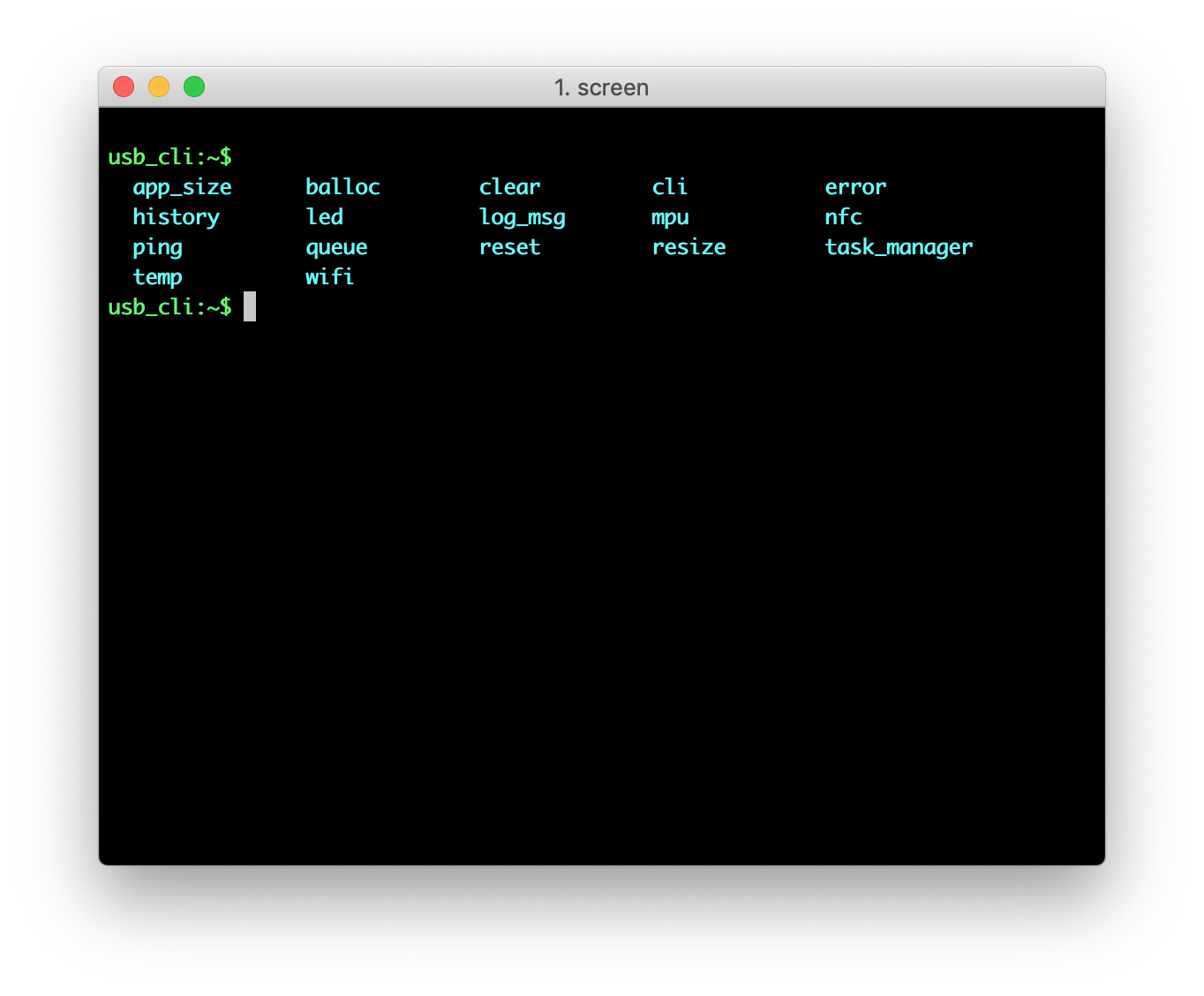
Start a terminal application. The default setup for the USB serial port is 115200 baud, 8 bits, 1 stop bit, no parity (115200-8-N-1). For example:
screen /dev/cu.usbmodemD2E39D222D781 115200Note
If you are using Windows 7 or earlier, you must load an additional USB CDC driver. The driver can be found in pitaya-go/external/usb_driver.
-
Press Enter on the keyboard to bring up the
usb_cli:~$prompt. -
Use the Tab key to print the available commands.
Set Up with Web Device CLI
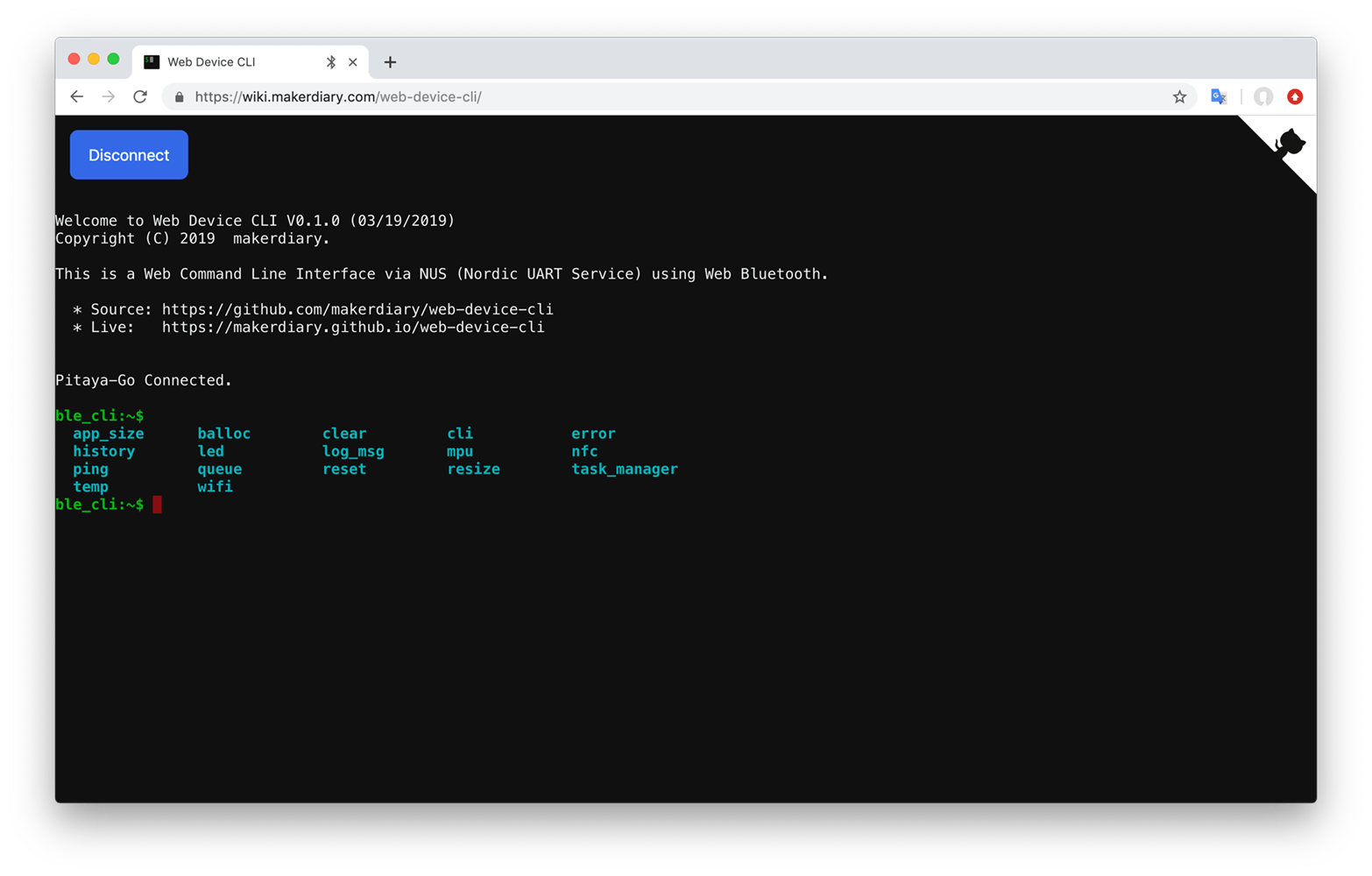
Web Device CLI is a web-based command line interface using Web Bluetooth API. It implements the Nordic UART Service (NUS) with Bluetooth Low Energy.
-
Open the Web Device CLI page in a Chrome 56+ browser.
-
Click Connect to scan devices.
-
Pair the Pitaya-Go discovered in the list.
-
Observe that the RGB LED stays GREEN and the
ble_cli:~$prompt is displayed. -
Use the Tab key to print the available commands.
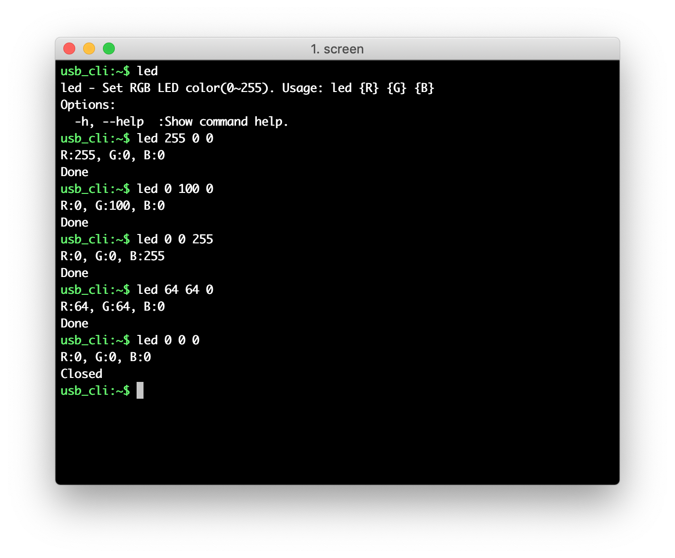
Set the LED Color
-
Use command
ledto print the command help information. -
Use command
led {R} {G} {B}to set the LED color. The parameters stand for the following:{R}: The RED value, 0 ~ 255.{G}: The GREEN value, 0 ~ 255.{B}: The BLUE value, 0 ~ 255.
-
Set various RGB values and observe the color of LED.
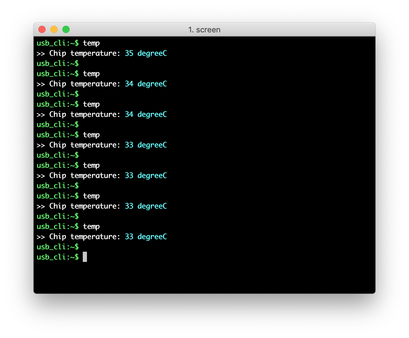
Get the Temperature
nRF52840 chip features a temperature sensor. The temp command is available for getting the chip temperature.
Control the NFC Tag
-
Use command
nfcto print the command help information. -
Use command
nfc startto enable the NFC. -
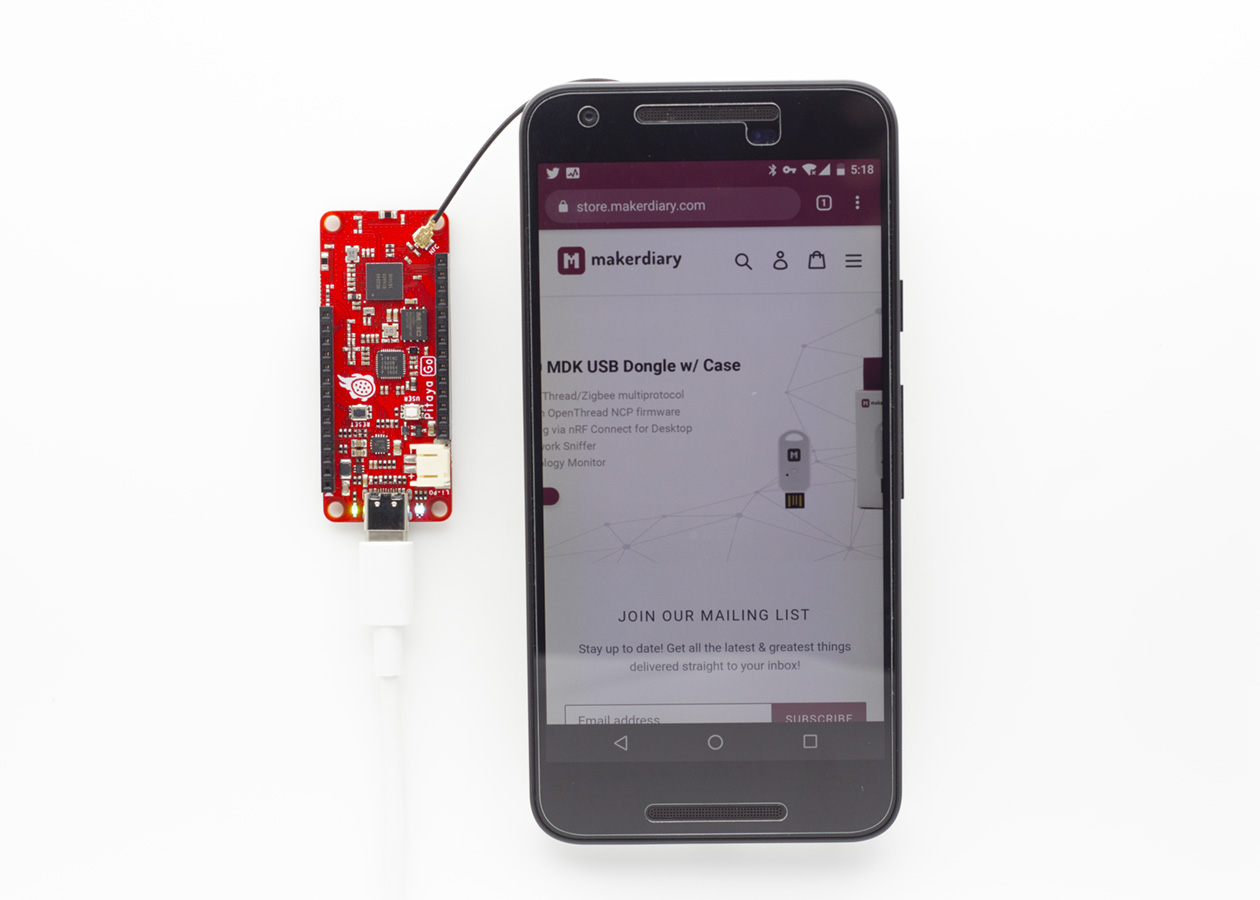
Touch the NFC PCB Antenna with the smartphone and observe that BLUE LED is lit.
-
Observe that the smartphone tries to open the URL https://makerdairy.com in a web browser.
-
You can also use
nfc stopto disable the NFC and usenfc statusto check the NFC status.
Connect to the Internet
Thie demo also allows you to connect to a Wi-Fi network via the CLI. Perform the following steps to connect to a Wi-Fi Access Point and check the Internet connectivity:
-
Use command
wifito print the command help information. -
Use command
wifi scanto the nearby Wi-Fi APs.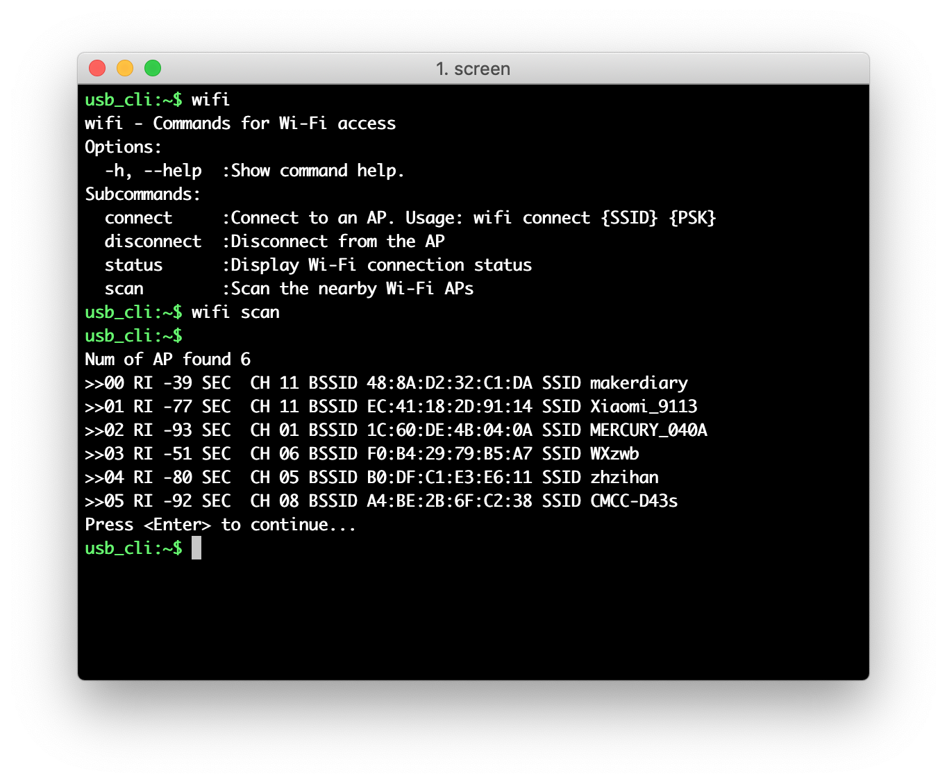
-
Use command
wifi connect {SSID} {PSK}to connect to your AP. The parameters stand for the following:{SSID}: The name of AP. If not specified, the device will attempt to reconnect to the last-associated AP.{PSK}: The passphrase of AP. MUST be 8 characters or more. If it's an Open network, it can be left blank.
-
Observe that BLUE LED is lit, that is, the Wi-Fi is connected. Use command
wifi statusto retrieve the Wi-Fi connection status. -
Use
ping {host}to check the Internet connectivity. For example, ping Google’s DNS8.8.8.8:ping 8.8.8.8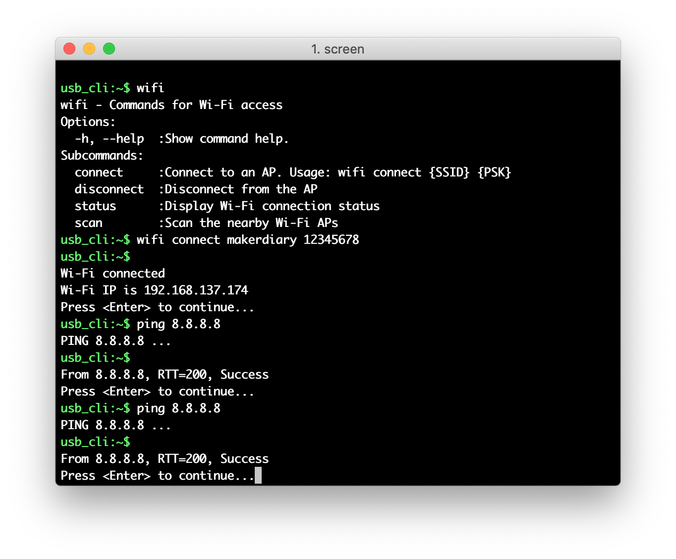
Explore Further
Now that you are familiar with the Pitaya Go, it's time to explore more examples and tutorials available below:
Create an Issue
Interested in contributing to this project? Want to report a bug? Feel free to click here: